


Why Grounding Matters for Test Equipment
Source: Probemart 2026-05-15 Views: 310
How does grounding affect test equipment such as oscilloscopes?
Test equipment such as oscilloscopes, signal analyzers, and frequency counters relies on stable grounding to operate accurately. Poor or unstable grounding introduces problems that affect measurement quality and safety. Let us take a closer look at how grounding affects various aspects of test equipment.
Test signal accuracy and stability
Stable grounding ensures that voltage readings remain consistent over time. When a signal lacks reliable grounding, it may fluctuate because of electrical noise or other environmental factors. This fluctuation is called signal drift and can make accurate measurement results difficult to interpret. For example, in an oscilloscope, unstable grounding causes the displayed waveform to shift up and down, making it difficult to accurately measure attributes such as peak-to-peak voltage or frequency.
Oscilloscope probe grounding issues can be resolved through accumulated probing experience.
Probe grounding is the low-impedance path through which current returns from the probe to the source. Increasing the length of this path creates a large common-mode voltage at the probe input at high frequencies. According to the following equation, the voltage generated behaves as if the path were an inductor:

Increasing ground inductance (L), increasing current (di) or reducing the transition time (dt) will all cause the voltage to increase(V). When this voltage exceeds the threshold voltage defined by the oscilloscope, erroneous data measurements will occur.
Sharing one probe ground with many probes forces all current flowing to each probe to return through that probe 's shared ground inductance (whose ground return is shared). The result is that the current in the above equation increases (di), and according to the transition time (dt), the common-mode voltage may increase to a level that produces erroneous data.
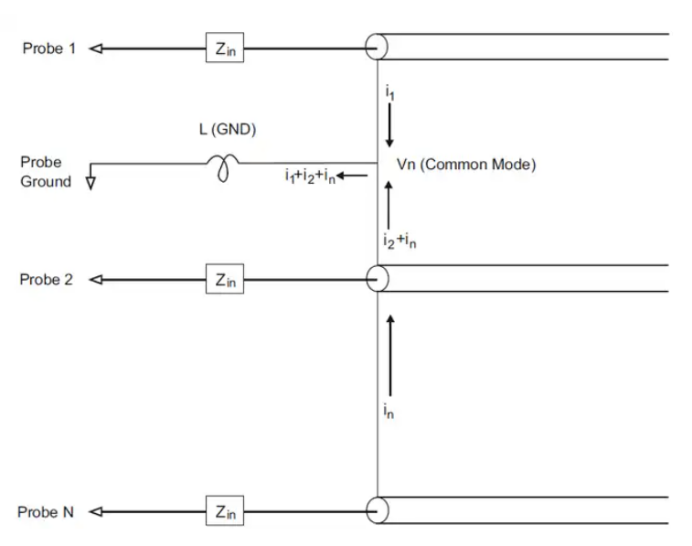
In addition to common-mode voltage, a long ground loop also degrades the pulse fidelity of the probe system. Rise time increases, and ringing due to the dry LC circuit also increases. Because digital channel displays reconstruct the waveform, they do not show ringing and disturbances. By checking the waveform display, you will not find grounding problems. In fact, problems may be found through erratic glitches or inconsistent data measurements. Use the analog channel to view ringing and disturbances.
Best probing practices
Due to the variables L、di and dt, you may not be able to determine how much margin is available in the measurement setup. The following guides you in developing good probing habits:
• If any channel in a group is used to capture data, the ground lead of each digital channel group (D15–D8 and D7–D0) should be connected to the ground of the device under test.
• When capturing data in a noisy environment, in addition to the channel group ground, the ground of every third digital channel probe should be used.
• High-speed timing measurements (rise time ) should use each digital channel probe's own ground.
When designing high-speed digital systems, you should consider designing dedicated test ports that interface directly with the instrument probe system. This makes the measurement setup easier and repeatable for acquiring test data.

Reduce ground loops and noise
When multiple ground paths exist in a system, ground loops occur; these loops pick up unwanted signals or electromagnetic interference (EMI). These ground loops cause noise interference, which may distort the signal and make it difficult to distinguish the true waveform. Impact on the oscilloscope: Ground-loop noise typically appears as random spikes or fluctuations on the waveform display, which can mask the actual signal and affect measurement accuracy.
Prevent voltage spikes and equipment damage
Test equipment is very sensitive to high voltages; grounding errors can sometimes produce voltage spikes that damage internal components. For oscilloscopes and other sensitive equipment, these spikes may cause permanent damage or lead to expensive repairs. Safety note: Ensure that the ground connections on the equipment are secure and reliable to reduce the risk of voltage surges. A reliable ground point provides a safe dissipation path for excess current, preventing potential harm to equipment and operators.
Improve signal fidelity and resolution
Signal fidelity refers to how accurately equipment captures the actual signal without distortion. Incorrect ground connections reduce fidelity, especially in high-frequency applications where noise has a greater impact. When fidelity decreases, measurement resolution also decreases, limiting the detail you can obtain from the waveform.
Isolated and differential measurements
In some test scenarios, a direct ground connection may interfere with the signal or even cause a short circuit. Differential probes or isolated measurement techniques do not require a common ground point while still maintaining measurement accuracy. In such cases, understanding the role of the ground point helps you determine whether direct grounding or an isolated measurement method is more suitable for your needs.
What is differential measurement? Grounded vs. Ungrounded measurement
Single-ended measurement with an oscilloscope probe, i.e., a measurement referenced to ground. This means that when using any probe, two points in the circuit must be connected to measure the voltage difference between them. For a single-ended probe, one of these points must be“ground”, which is usually connected to earth ground through the oscilloscope.
Single-ended probe = Ground-referenced probe
•When using any probe, the two probe inputs must be connected to a circuit to measure the voltage difference between them。
•Single-ended measurement is the voltage difference between the input signal and ground. For a single-ended probe, one of the points must“be grounded”. The difference is fed to the oscilloscope input.
•Single-ended inputs may be affected by noise or ground bounce problems because the signal-carrying wire picks up electronic background noise。

One problem with a single-ended probe is that the wire carrying the signal picks up electrical noise, so it may be affected by noise or ground bounce.
Differential measurement = Ungrounded measurement
If you want to measure the voltage difference between two points and neither point is“ground”, what should you do?
You need a probe with no“ground”connection. This is called a differential probe. In this circuit, neither end of the middle resistor is at0V, so it is“floating”. This means that if we measure its voltage with a single-ended probe, the circuit will be grounded——This is very dangerous and will damage the circuit!

•If you want to measure the voltage difference between two points but neither is“ground”What should I do??You need a probe that can measure non-grounded signals effectively.。
•The main advantage of a differential probe is high common-mode noise rejection, because noise is added to both wires simultaneously and can then be filtered out by the common-mode rejection of the differential amplifier.。
Reprinted from Keysight Technologies

PCIM Europe 2026, Nuremberg: IWATSU and PMK at Booth H7-157
2026-06-15
APEC 2026: 41st IEEE Applied Power Electronics Conference and Exposition
2026-03-15
Semicon China 2026, Shanghai New International Expo Centre (SNIEC)
2026-03-11
WiPDA Asia 2025, Beijing International Convention Center, 15 August
2025-08-06