


Danisense DCCT Ultra-Precision DC Current Sensors: How They Work
Source: Probemart 2024-01-03 Views: 4059

Current sensor basics
Without electricity, what would we do? Nothing! This energy is everywhere, and the energy transition and decarbonization under way in our industry are driving more electrification of all our daily activities (such as electric vehicles). As with any physical quantity, if you do not measure it, you cannot manage it! In fact, in any process, measurement is essential for monitoring, metering, and control systems, and a current sensor is needed for this.
Primary and secondary currents
Basically, a current sensor is a device that converts the current signal we want to measure (called the primary current) into another signal (called the secondary current or voltage) that can be used by an electronic control board or instrument. Because the primary current may vary (AC or DC, from a few mA to kA, isolated or non-isolated, etc.), there is a wide variety of current sensors using the different technologies described below.

Fluxgate current sensor
Generally, the principle of a fluxgate is to use an excitation coil with magnetic material as the probe. Owing to saturation/desaturation cycles and signal processing, this coil can measure the magnetic field proportionally. This allows various current sensor designs. It can simply replace a Hall-effect probe in an air gap, or the coil can have a split shape.
High accuracy
For more details, we invite you to read the detailed article on thefluxgateprinciple.
How does a current sensor work?
Measuring current directly is a rather challenging task. This is usually simplified by measuring side effects of the current flow, such as measuring the voltage drop across a resistive shunt (Ohm's law) or measuring the magnetic field around the primary conductor (Ampere's law).
Current measurement using a resistive shunt is very simple, but it requires the user to interrupt the primary circuit to insert the shunt, provide suitable cooling for the shunt, or at least properly size the shunt for the required current range; the disadvantage is that the current measurement signal is not isolated from potentially hazardous primary voltage levels.
The advantage of current measurement using the generated magnetic field is that it is non-contact, i.e., isolated current measurement, so there is no need to insert lossy components such as a shunt resistor to interrupt the primary circuit. The magnetic field generated by the current through the primary conductor is proportional to the applied current and therefore carries information about the current amplitude.
The way the measured magnetic field is converted into current amplitude information will depend on the measurement principle (link to 'What are the different types of current sensors'), but the common advantage is that the current measurement is fully isolated from the main power circuit, which generally makes the important tasks of controlling and protecting complex electrical systems easier to handle.
DC current sensor
Not every current measurement principle based on Ampere's law can measure DC current. For example, inductive current sensors and Rogowski coils rely on magnetic induction, where an alternating/AC magnetic field induces current and voltage in the coil, and in practice cannot measure DC current.
Magnetic probe
Magnetic probes capable of sensing DC magnetic fields, such as Hall-effect probes, fluxgate probes, and magnetoresistive probes, can be used to build DC current sensors (commonly referred to as DCCTs).
Open-loop and closed-loop current sensors
Open-loop and closed-loop are both possible, but in an open-loop CT, applying a strong DC magnetic field can premagnetize the core, thereby significantly affecting AC current measurement performance, while taking into account the common nonlinear B-H curve.
AC current sensor
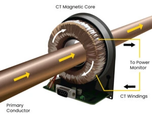
AC current transducers, also known as AC current transformers and commonly abbreviated as “CT,” are widely used as current-sensing transformers in power grids, such as generators or substations. Their function is to scale the measured current down to a lower measurement level and provide essential isolation from high-voltage power lines.
The basic form of an AC current transformer consists of a magnetic core, usually toroidal, wound with a wire called the secondary winding. At the opening of the toroidal core, the primary current passes through. The operating principle of an AC current sensor is Faraday's law of induction, which states that a change in magnetic flux induces a voltage in the inductive winding. This means that an AC current sensor can only measure AC signals. An AC current transducer is usually a passive device used with a shunt to detect the secondary current in the output signal.
Current Sensor – Operating Principle
The operating principle of an AC current sensor is Faraday's law of induction, which states that a change in magnetic flux induces a voltage in the inductive winding. This means that an AC current sensor can only measure AC signals.
An AC current transducer is usually a passive device used with a shunt to detect the secondary current in the output signal.

PCIM Europe 2026, Nuremberg: IWATSU and PMK at Booth H7-157
2026-06-15
APEC 2026: 41st IEEE Applied Power Electronics Conference and Exposition
2026-03-15
Semicon China 2026, Shanghai New International Expo Centre (SNIEC)
2026-03-11
WiPDA Asia 2025, Beijing International Convention Center, 15 August
2025-08-06